
12/07: Day 7 🎄
Refresh and Reload: Secrets of the Unified Buffer


Welcome back to Unwrapping TPUs ✨!
Last post, we took a brief detour into the world of numerics to better understand why Accumulators were handling 32-bit data and how they came to be perfectly packaged into 8-bit streams for the Unified Buffer (via Post-Training Quantization), thus introducing the last core piece of the TPU v1’s computation flow.
Today, we implement the feedback dataflow details of Accumulator to Activation Pipeline to Unified Buffer in our tiny tiny TPU!
Main Computation: Feedback Dataflow
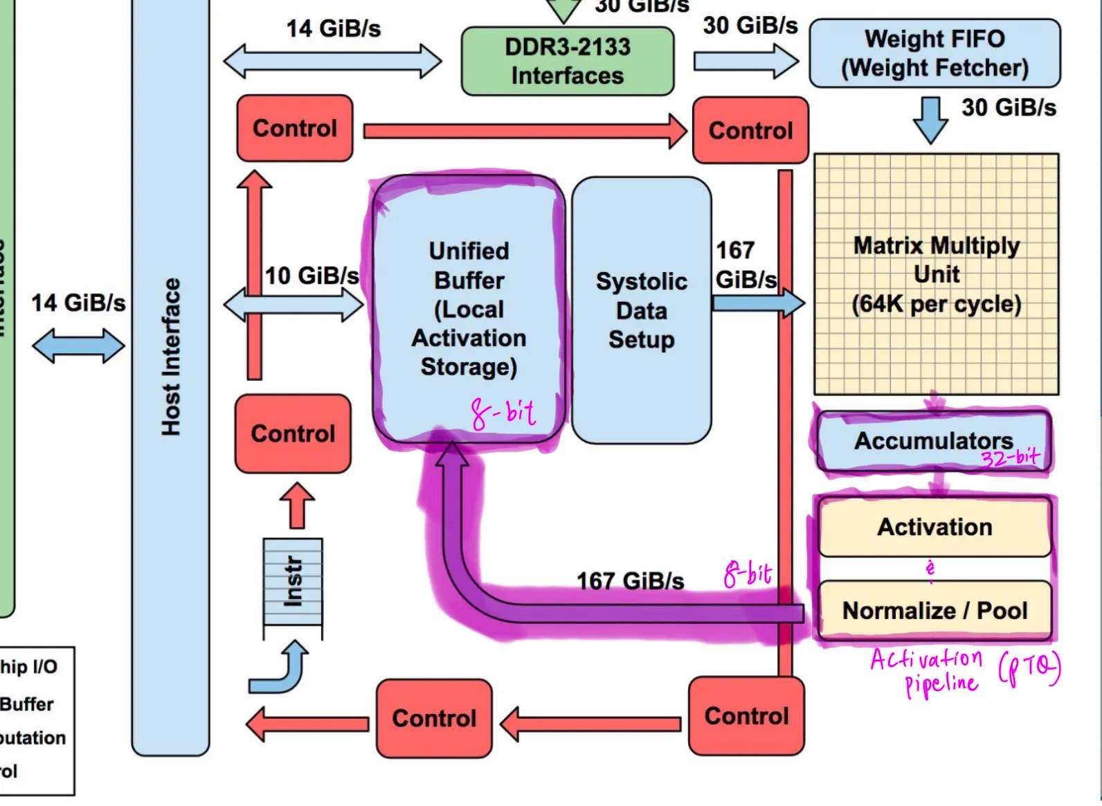
The provided diagram, with the dataflow highlighted in Purple (snazzy, right?) was referenced and helps clarify our specific terminology used in describing the TPU v1 dataflow feedback (Jouppi et al.).
As part of the TPU’s main computation path, the Accumulator kickstarts a critical feedback in dataflow, refilling the Unified Buffer and helping saturate the MMU with updated activation data inputs.
MMU → Accumulator → Activation Pipeline → Unified Buffer → MMU → repeat…
We start in the Accumulator’s double-buffered 32-bit results, which are passed to the Activation Pipeline (Activation and Normalize Blocks on the left) for Post Training Quantization (PTQ). Subsequently, the quantized results are now 8-bits and passed into the Unified Buffer.
Let’s first break down the Accumulator.
Accumulator
Previously, we’ve covered the Accumulator’s role in passing 32-bit results from the MMU to be quantized 8-bit results in an effort to replenish the Unified Buffer.
In the case of our tiny tiny TPU, since we’re working on a 2 x 2 systolic array, we have to make a couple minor adjustments. Doing some quick math, since we’re working with 8-bit activation data and 8-bit weights, the max value of MAC products is 255^2. This fits nicely in 16 bits as the log_2(255^2) = 15.99.
Passing these partial 16-bit product sums through the systolic array, although we don’t have 256 rows to go through, the maximum end sum at the very end of the MMU is 255^2 * 2 = 130,050. When taken to the log base 2, this value resolves into 16.99, still requiring 32 bits of precision like the full scale TPU.
However, when looking at the net dimensions of the TPU v1 Accumulator, we clearly don’t have a need for a depth of 4096. Further, the systolic array dimension we’ve implemented is 2 x 2 not 256 x 256. Since we still want to carry a double buffering effect, we design for a depth 2.
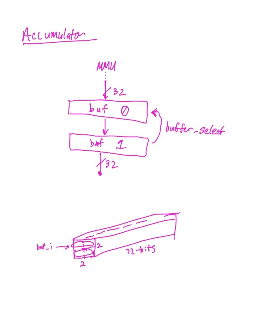
For the two columns in our 2 x 2 systolic array, we have another dimension of 2. This makes our Accumulator of 2 x 2 x 32 bit dimension (much more compact than the full TPU v1’s 4 MB!).
Double-buffering MMU results into the Accumulator works similar to the Weight FIFO scheme we’d mentioned prior. The Accumulator holds two 32-bit buffers that cycle out such that one is receiving inbound data from the MMU and one is passing along information at all times, selected in our code using “buffer_select”.
Once selecting the buffer to input data into, the beauty of a systolic array is that we also need to align the results such that results are streamed in as diagonals, just as the activation inputs and weight FIFOs are staggered. Thus, at time t=T, column 0 results arrive, and at time t=T+1 column 1 results arrive, allowing the buffer to be shipped out.
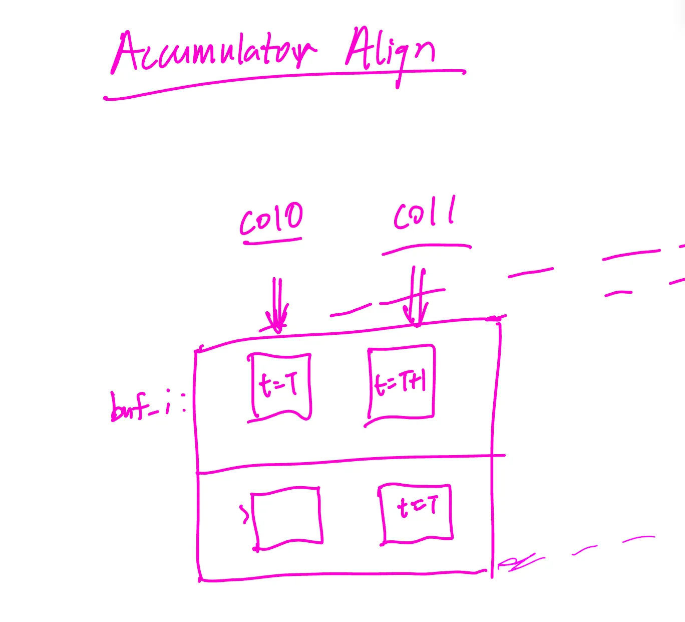
The accumulator memory module takes the column-aligned input into the buffer and zero pads such that the results are all 32-bits to be passed now to the Activation pipeline.
Activation Pipeline
The goal of the activation pipeline is to take the 32 bit accumulator outputs, apply activation, normalization, and loss. Within this process, the activation pipeline will quantize 32 bit floats to int8 for input into the unified buffer.
Considering the dataflow we’ve already covered: the pipeline first applies a fixed ReLU stage (activation_func.v).
Next comes fixed-point normalization in normalizer.v: we multiply the 32-bit value by a 16-bit gain, keep the full-width product (48 bits) so it can’t overflow, then right-shift by shift (a power-of-two scale) and add a 32-bit bias. This adds one cycle of latency and keeps the valid tag aligned.
In parallel with quantization, it computes loss (loss_block.v) as an L1 error. This target is registered once in activation_pipeline.v so it lines up with the normalized value in time.
Verification backs this up: the unit testbench activation_pipeline_tb.v scoreboards activation → normalization → quant → loss across clamp, saturation, scale, and bias cases.
In the full-chain integration TB (accel_integration_tb.v), the pipeline sits between the accumulator and unified buffer, with UB backpressure gating input; the UB stream matches the scoreboard (e.g., 10, 0, 30, 30, 35, 35) and runs clean. Supporting TBs for the accumulator and unified buffer also pass, confirming alignment, accumulation, and ready/valid flow control.
Unified Buffer
The unified buffer is a synchronous ready/valid FIFO that carries 8-bit activations from the pipeline to a downstream consumer. It sits after the activation pipeline, which itself is fed by an accumulator that aligns staggered MMU-style inputs (col0 then col1) into 32-bit sums. Inside the buffer, a circular memory, read/write pointers, and a count track occupancy; full and empty come straight from that count.
A write happens only when wr_valid is asserted and the buffer isn’t full, storing the incoming byte, advancing the write pointer, and incrementing count. A read happens only when rd_ready is asserted and the buffer isn’t empty, presenting the oldest byte, pulsing rd_valid, advancing the read pointer, and decrementing count.
Reads and writes can occur in the same cycle, and reset clears pointers, count, and outputs so the buffer starts empty. Backpressure is automatic: wr_ready drops when full to stall the activation pipeline, and rd_valid drops when empty to tell the consumer to wait. Width and depth are parameterized to match throughput and storage needs.
The testbench drives staggered accumulator outputs through the activation pipeline and into the unified buffer, then drains the buffer with controlled rd_ready. It fills to full, drains to empty, and asserts that no write occurs when full and no read occurs when empty. A scoreboard records every accepted write (on wr_valid & wr_ready) and checks every read (on rd_ready & rd_valid) for correct ordering; any mismatch triggers $fatal.
These checks pass, confirming that flow control, ordering, and handling of staggered upstream inputs behave correctly end-to-end.
Putting it all together
We instantiate the RTL, drive it with ready/valid stimulus, and use a scoreboard to model expected behavior. For units, we log what the DUT accepts (valid & ready), compute expected outputs in the TB, and $fatal on mismatches or protocol violations.
For integration, the whole chain (accumulator → activation pipeline → unified buffer) is wired, UB backpressures the pipeline, and every byte written into UB is recorded and later checked against reads; any mismatch triggers $fatal.
The integration testbench (accel_integration_tb.v) drives all components together: accumulator → activation pipeline → unified buffer—under ready/valid control.
MMU inputs (col0 then col1) enter the accumulator; the aligner pairs them, and the mem overwrites then accumulates, emitting 32-bit sums (acc0, acc1) with acc_valid. The activation pipeline applies fixed ReLU, fixed-point normalization (norm_gain, norm_shift, norm_bias), optional loss (ignored here), then affine quantization using q_inv_scale and q_zero_point to produce ap_data with ap_valid.
The unified buffer accepts ap_data when ub_wr_ready is high and later outputs via ub_rd_valid/ub_rd_data when rd_ready is asserted, exposing ub_full/ub_empty for status. We implement these in Verilog with a testbench that instantiates each module, connects the ports directly, gates the activation input with ub_wr_ready for backpressure, asserts rd_ready to drain the buffer, and uses a scoreboard to compare every UB read against what was written on ap_valid & ub_wr_ready, with $fatal on any mismatch.
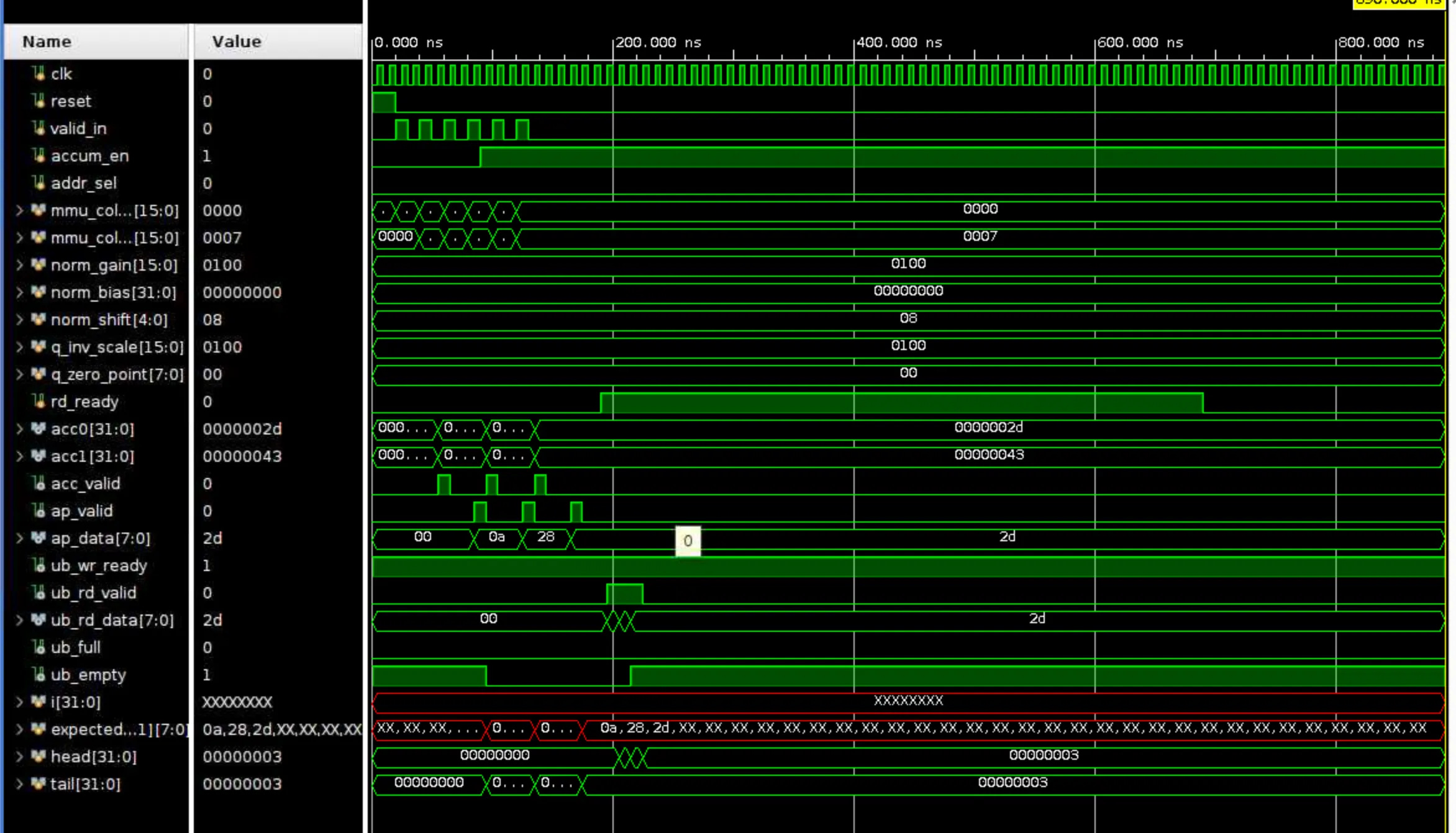
On the waveform, you can see the stimulus pulses valid_in during the early cycles; accum_en switches from overwrite to accumulate; configuration buses stay constant (unity scale, zero bias, zero-point). acc0 and acc1 show the aligned and accumulated 32-bit values; acc_valid and ap_valid pulse as data propagates through alignment, normalization, and quantization. ap_data shows the int8 outputs (e.g., 0x0a, 0x28, 0x2d), and ub_wr_ready remains high so the pipeline isn’t stalled. Later, rd_ready goes high to drain the buffer; ub_rd_valid/ub_rd_data reflect the readouts, and ub_empty deasserts/reasserts as data is consumed.
The red-highlighted array (expected[...]) and the X’s correspond to uninitialized scoreboard entries beyond what has actually been written. Only indices below tail are meaningful; indices above remain X until written. The TB checks matches only for the range head < index < tail, so the X-filled tail of the array is benign. head and tail counters track consumed vs. produced expected entries; both end at 3 in the shown run, indicating all produced items were consumed without mismatch. If there were a protocol or data error, the TB would $fatal at the first bad comparison (e.g., read when no expected data or value mismatch).
Code Implementation
Take a look at our GitHub repo (the same one as usual) to look at the implementation! Excited to continue and complete this teensy eensy TPU. https://github.com/Alanma23/tinytinyTPU
We hope you’re just as excited to join us for the ride!
Works Referenced
Jouppi et al. In-Datacenter Performance Analysis of a Tensor Processing Unit